


Share by email
Your message was succesfully sent!
Add The Following Snippet To Your Html


DETAILED DESCRIPTION
Summary
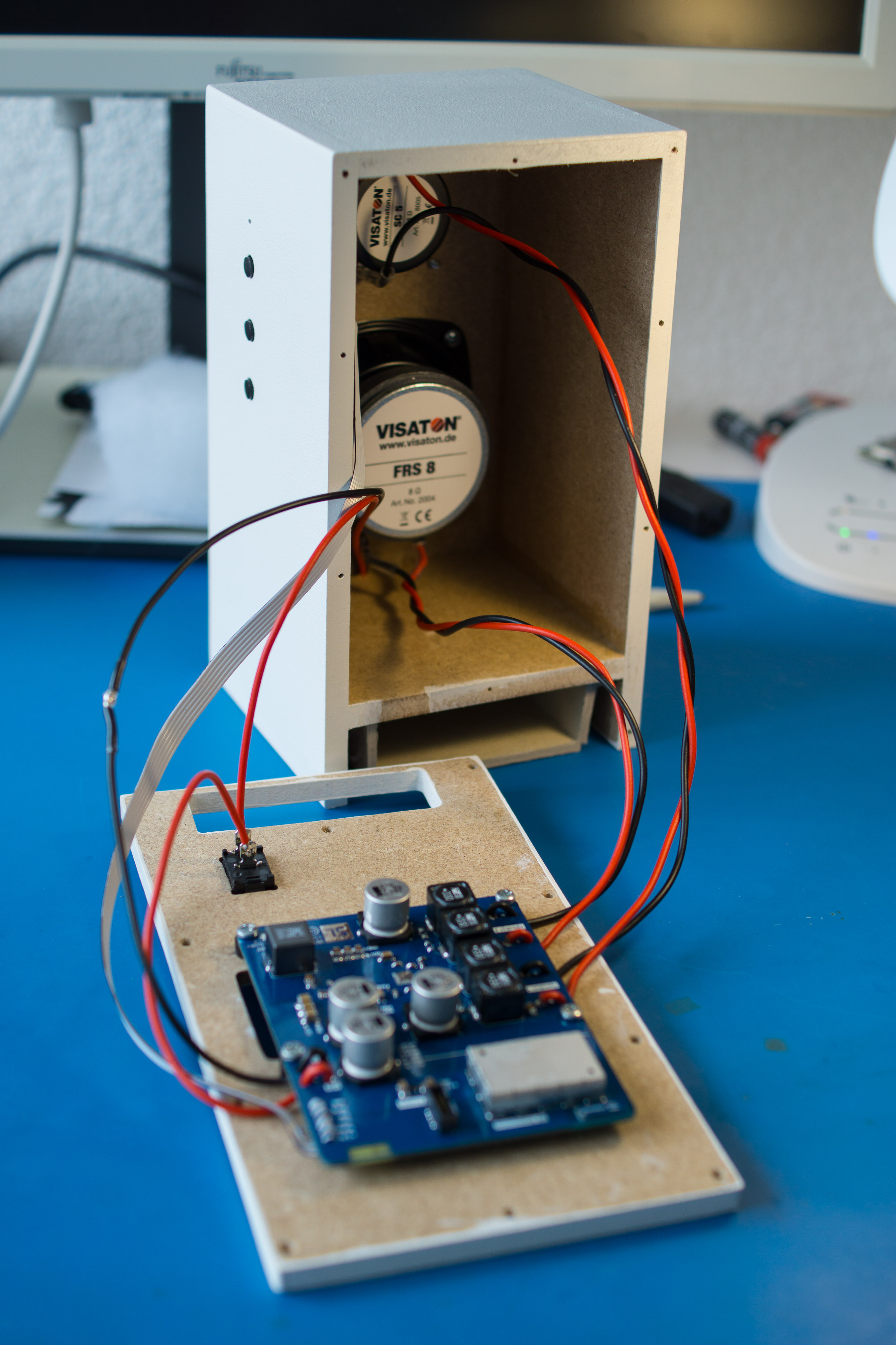
The Wireless Speaker is an addition to the Digtial Audio Transceiver. It uses the same tranceiver IC (TI CC8531). However, the TI TAS5710 is used as an audio output. The goal is to build a small wireless speaker that is battery powered.
Components
The schematics can be divided into the following components.
Power Supply
The device uses two power rails: 3.3V for all the digital ICs and the transceiver and 20V for the audio output stage.
3.3V is provided by MAX8511EXK33+T, a low noise LDO regualtor.
For the 20V rail TI TPS43061 is used, a switching regulator with external transistors. The design was done by using TI WEBENCH. The link for the design project can be found in the external links section.
RF Transceiver
This part was copied from the Digital Audio Transceiver, thus stays the same.
Speaker Amplifier
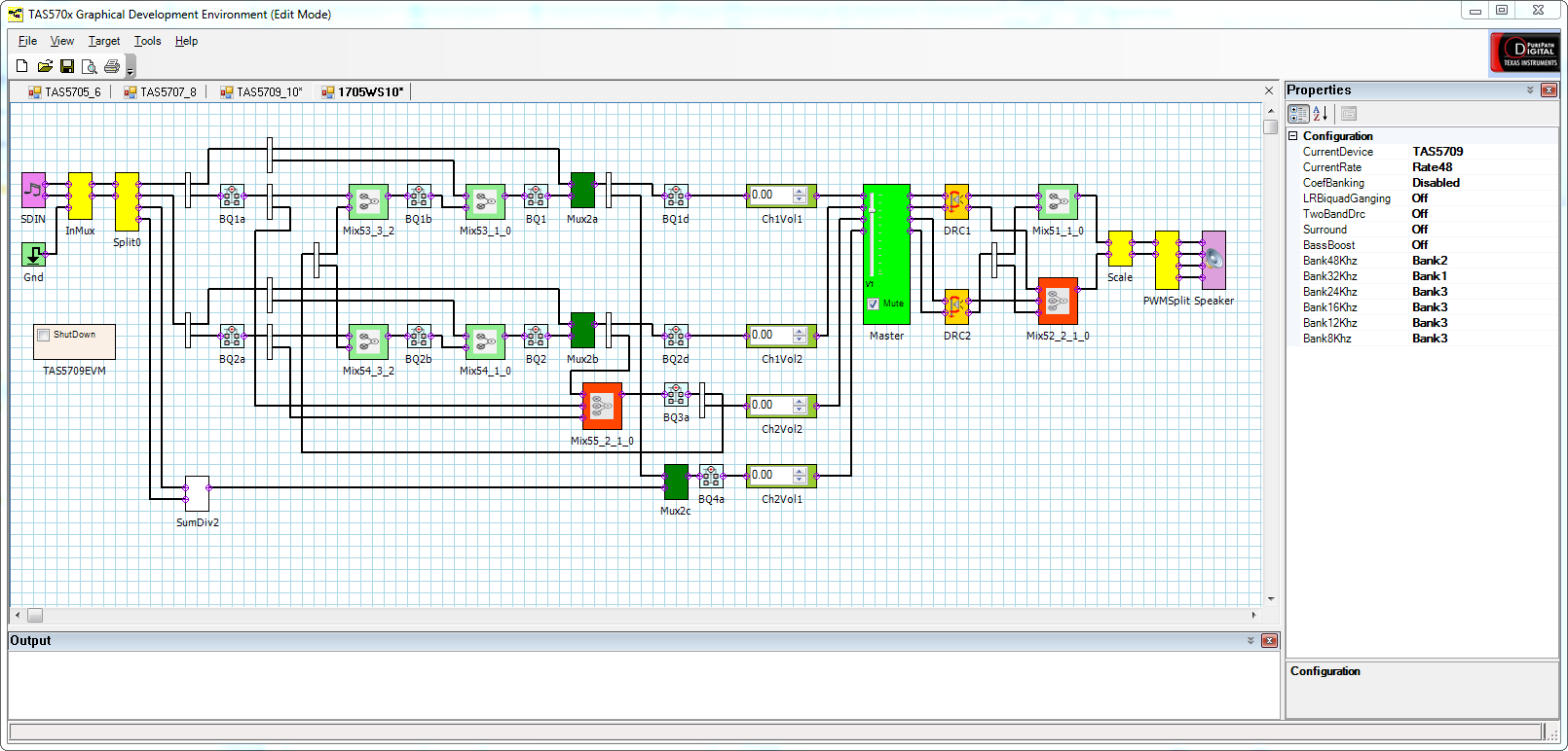
The TAS5710 is an audio amplifier with integrated digital filters which can be configured over I2C. The audio stream is injected over I2S and the amplifier drives two 8Ω speaker driver. The amplifier belongs to the Class D, which means that it outputs a PWM signal. This signal is filtered by an inductor and an capacitor.
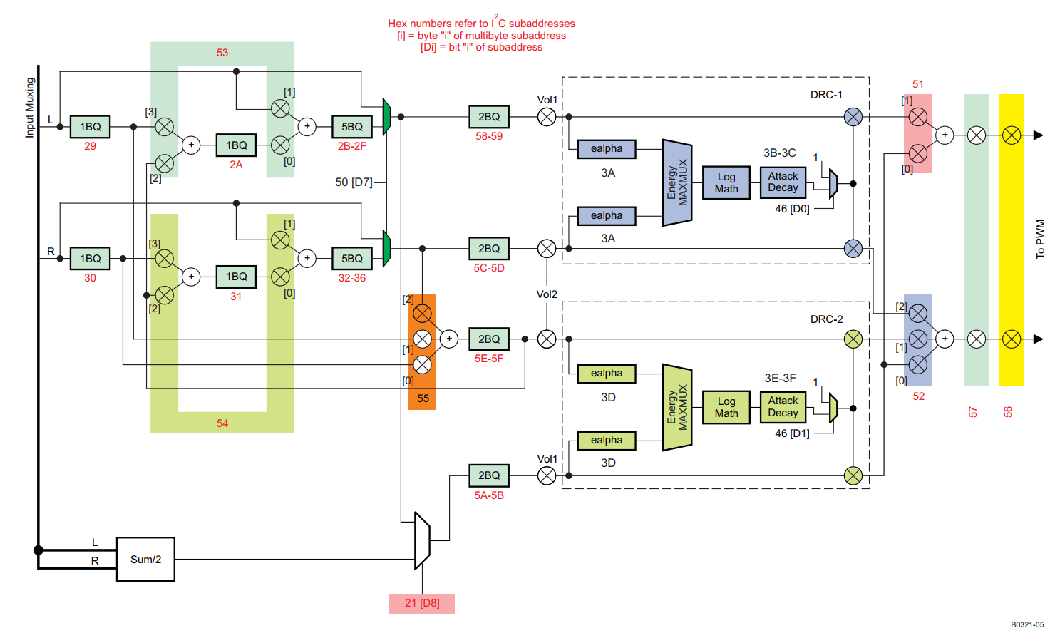
The image shows the internal signal path of the amplifier. Because the wireless speaker is a mono output device both audio channels are mixed at the beginning. Then they are filtered for highs and mids/bass. Finally some EQ balancing can be applied.
Please note that this is a fairly old chip there might be better ICs on the market. But this IC is supported by default in the Pure Path Wireless Configurator.
Mechanical Design
At first the the volume of the enclosure was determined and it was then designed in Fusion 360.
Encolsure Volume
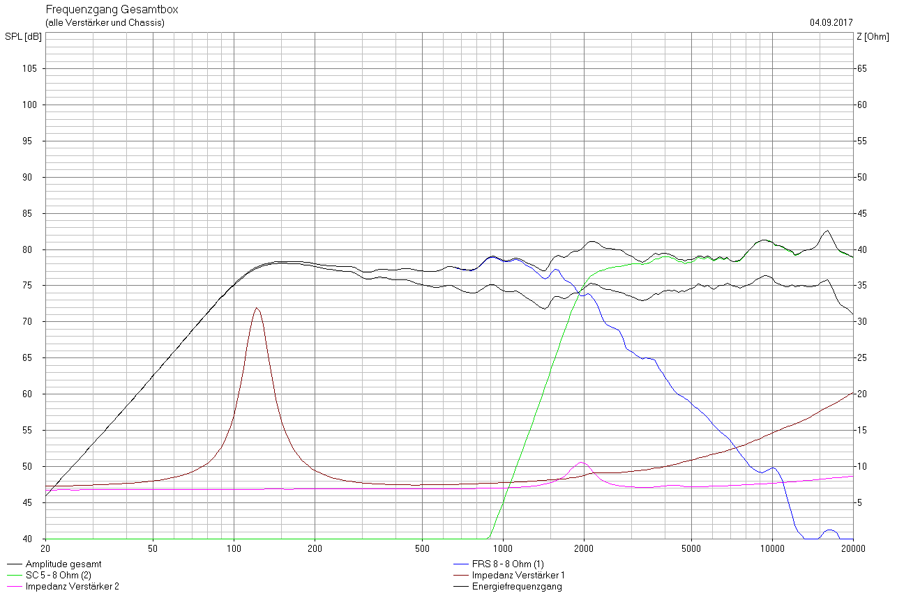
Visaton offers a great speaker simulation tool for their speaker drivers called Boxsim. With this tool I was able to select my speaker drivers and calculate a reasonable volume for my speaker. As speaker drivers I've chosen the Visaton FRS-8 for the mids and bass as well as the Visaton SC-5 for the highs. With a volume of 1.6l this should result in the following frequency response.
The simulation file can be found in the attachments.
Design in Fusion 360
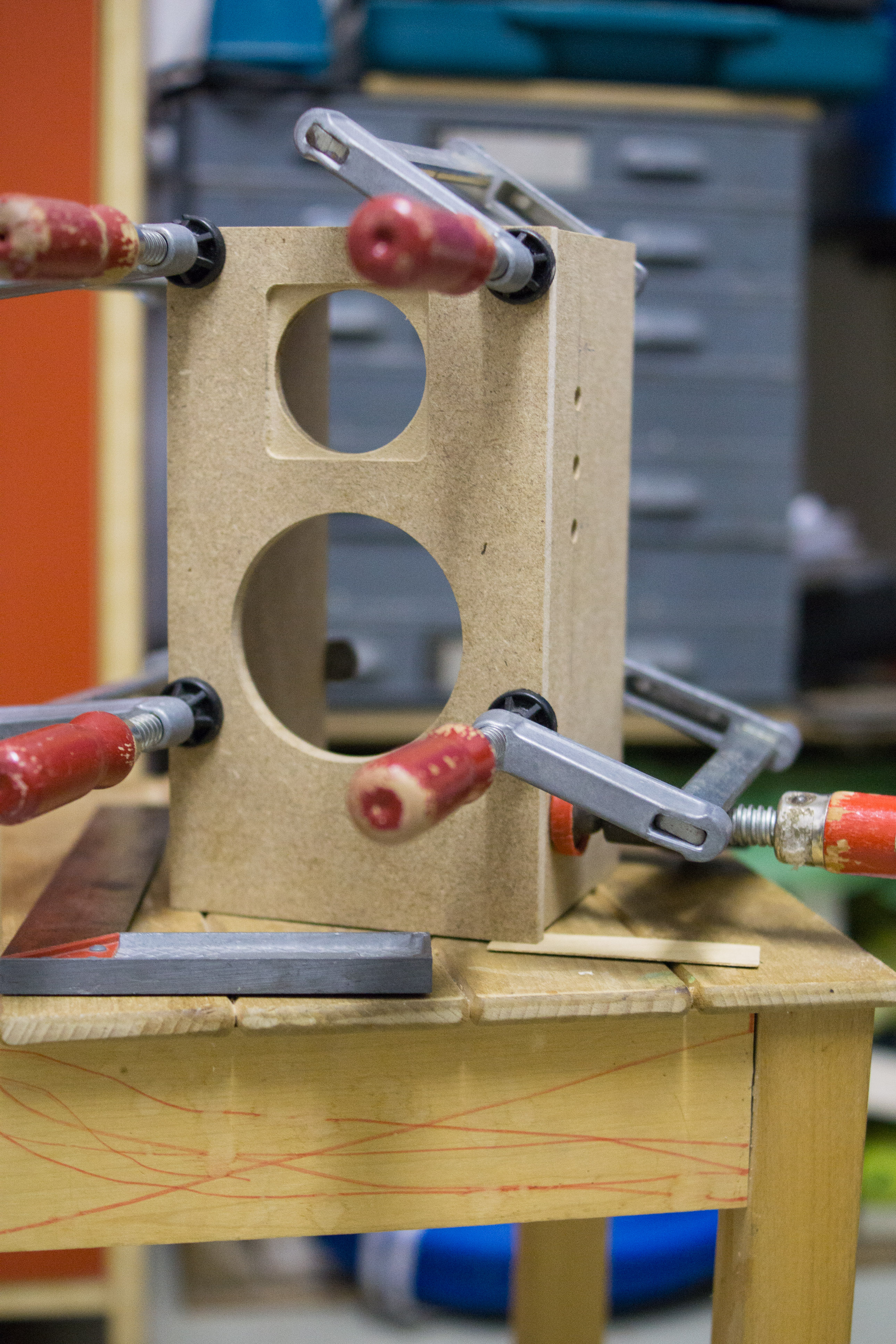
For the mechanical design I exported the STEP model of the PCB and imported that file into Autodesk Fusion 360. At first I had to model the speaker drivers and the battery pack. The goal was to design the enclosure using pieces of MDF and to reach a volume of approximately 1.5l. All the pieces except the backplate should be glued to together. The blackplate should be removable for easy maintance. With these considerations in mind I started the design process.
Manufacturing
I picked-up some MDF at the local hardware store and started milling them on my router. Fusion 360 allowed me to generate the toolpath for the router. At the end some slots and holes were too small (I didn't add enogh clearance) which had to be sanded to the final dimension.
With all the pices finished I could glue them together ...
... and sand off the edges.
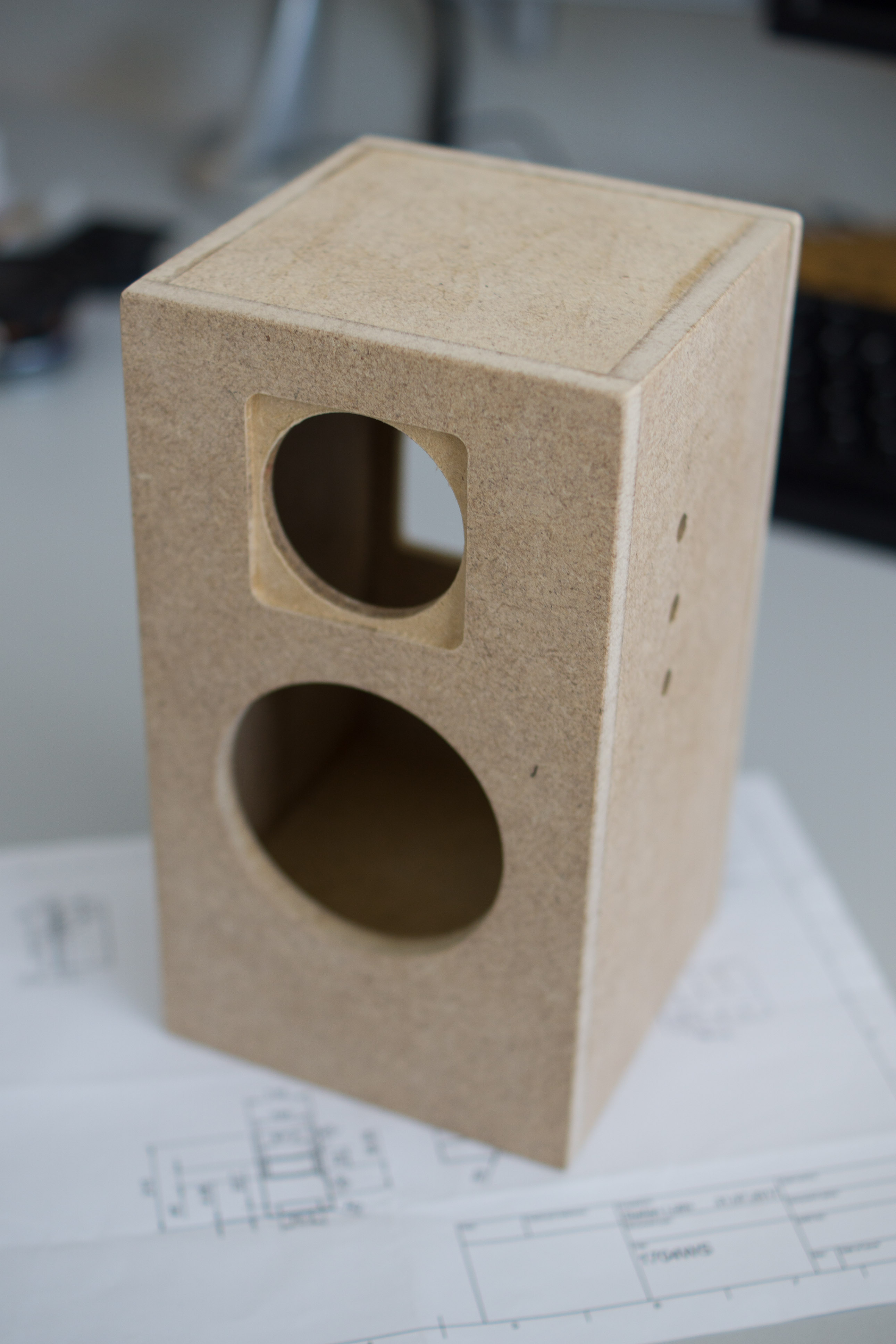
The case was then painted and the components were intalled.
Firmware
The firmware was again generated using TI Pure Path Wireless Configurator and TI TAS570x Graphical Development Environment. TAS570x GDE allows to generate the configuration data for the internal filters of the audio amplifier.
The filter configuration is implemented in the PurePath Wireless Configuration file which can be found in the attachements.
Design Review V1.0
During the schematics process three simple mistakes were made. The errors are now eliminated in the new schematics version. However, they still exist on the PCB.
Q201 flipped
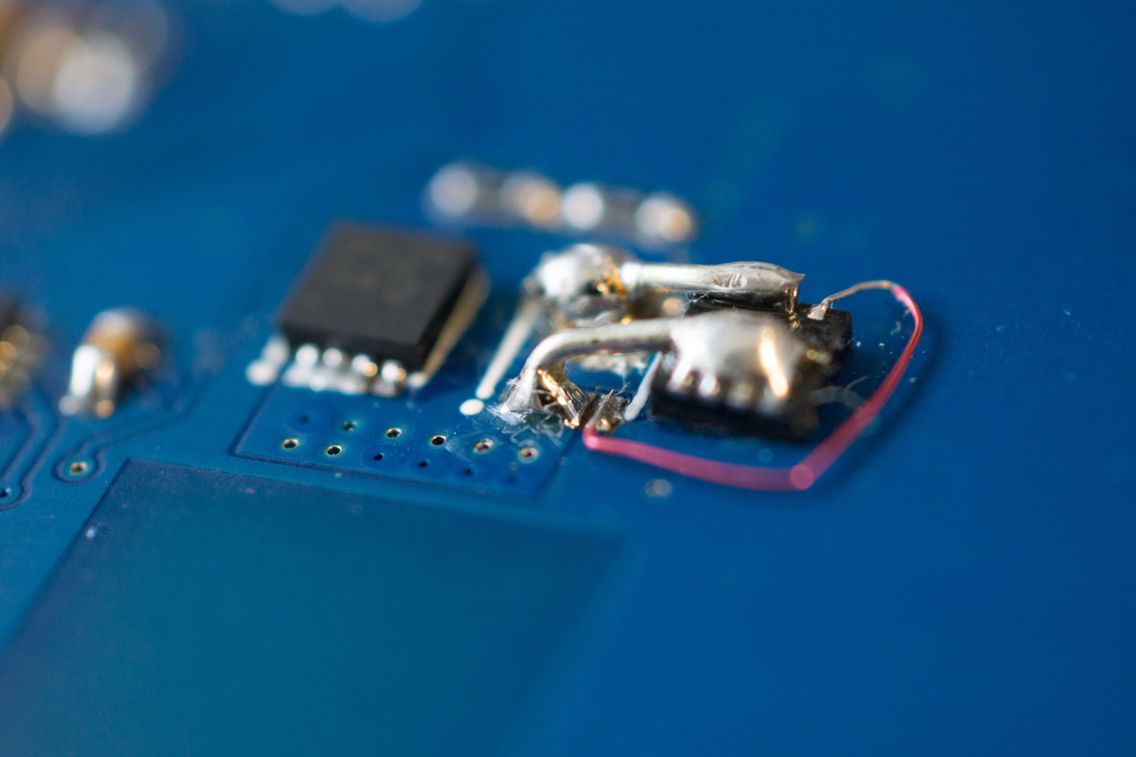
Q201, the power MOSFET for the 20V switching regulator has been put upside down in the schematics. Thus the drain and source connectors were interchanged. To resolve the issue the transistor was glued onto to PCB and then wired by hand.
Missing Pull-Up Resistors on I2C Bus
I've forgot to place the pull-up resistors on the I2C bus.
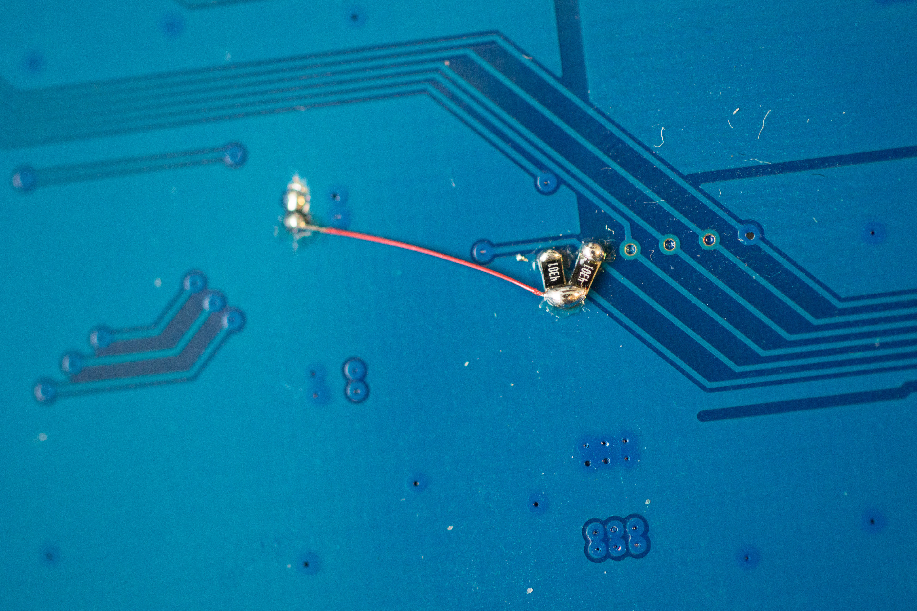
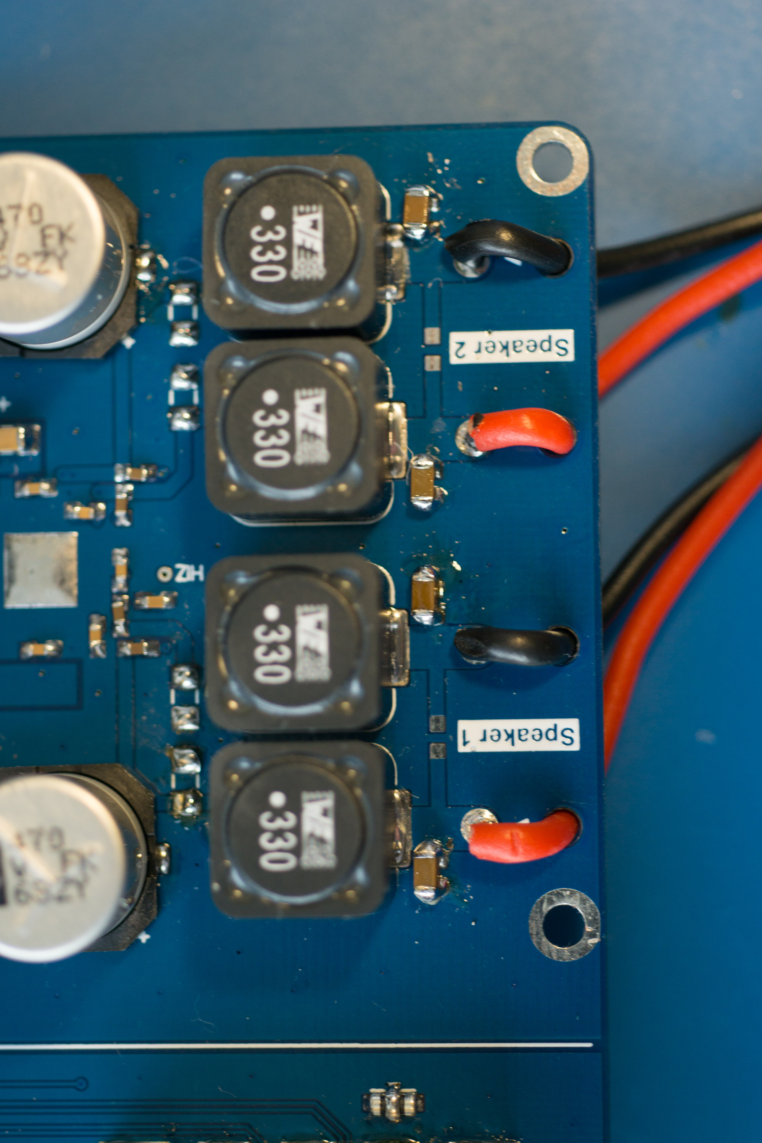
Filter Capacitors on Audio Output
The filter capacitors should be placed after the inductor. On the picture you can see the original placement on the left of the inductor. After I discovered the mistake I put them on the right side. Lukily I had some DNP components for additional capacitors there.
Comments on the Design
- The 20V 2.5A switching regulator is most probably an overkill
- The audio output filter inductors (L400...L404) are oversized
Current Project State
The speaker is finished and in use. The sound is mostly good, however, it si lacking some bass due to the closed style enclosure.
Design files
Authors
- /
- Active Participants


Components & Releases
Fabricate
Delete release
Are you sure you want to delete this Release?
This action cannot be undone.
Unable to download from CircuitMaker
You cannot download files inside CircuitMaker.
Please, open this page in browser and download file from there.
To copy hyperlink, press Ctrl+C with selected text below:


Comments ()